| AN 01-25CN-2 | PARAGRAPH 7 | |
| SECTION IV |
 |
||
|
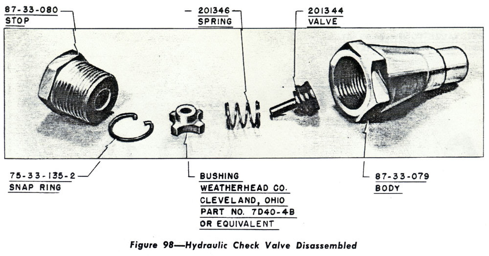
3. TO ASSEMBLE THE CHECK VALVE. a. Inspect the valve body and other parts for grit, dirt, or other foreign matter. Clean the valve and parts thoroughly with alcohol and blow out with compressed air, if available. b. Replace the valve, spring bushing, and snap ring in the valve body. c. Screw the stop nut onto the valve body and tighten. (g) HYDRAULIC RELIEF VALVE. 1. GENERAL.-One single relief valve for the hydraulic auxiliary hand pump (Drawing 87-33. 066) and one twin relief valve for the landing gear and flap controls are located in the lower left side of the fuselage forward of the access door. Another twin relief valve (Drawing 87-33-069) is located in the lines to the control valve midway between the control valve and cockpit floor. 2. To disassemble the twin relief valve, disconnecting the hydraulic lines to the valve, |
remove the valve from the airplane, and proceed as follows: Loosen the two lock nuts and turn out the screws. After the set screws are removed, the two springs and plungers will drop out. (See Fig. 99.) 3. TO ASSEMBLE THE TWIN RELIEF VALVE. a. Clean the valve thoroughly with alcohol and blow out with compressed air if available. Inspect the needle points on the plungers to be sure that they have not been dropped on the points or damaged in some other manner. b. Drop the plungers into the valve first and then the springs. c. Insert the set screws with gaskets and lock nuts and tighten the set screws. Lock the set screws with the lock nuts. Set the valve to by-pass at 1800 to 2000 p.s.i. d. Reinstall the relief valve in the airplane and connect the hydraulic lines. |
|