| AN 01-25CN-2 | PARAGRAPH 1 | |
| SECTION IV | ||
| MAJOR COMPONENT PARTS AND INSTALLATION |
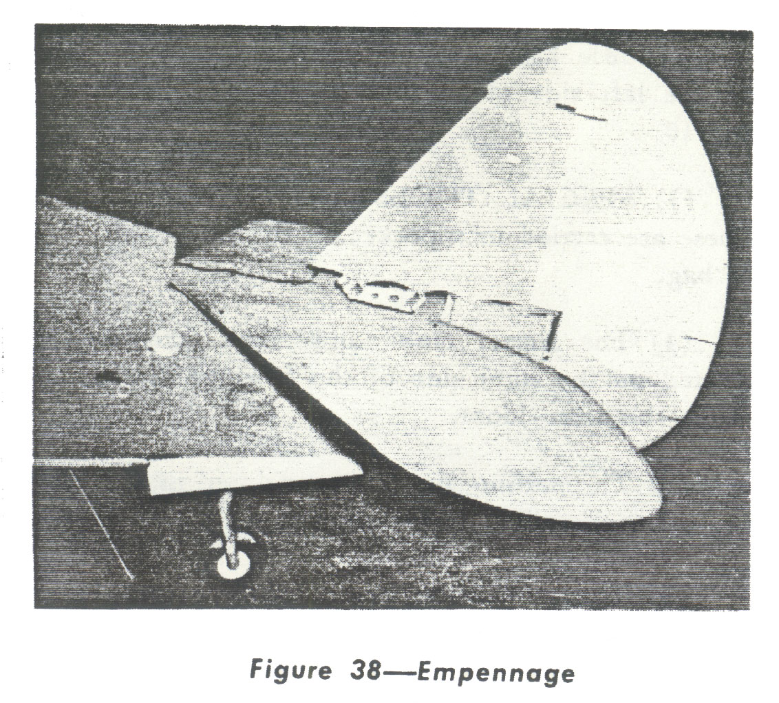
by a series of eight vertical bolts. The vertical stabilizer is attached to the horizontal stabilizer and the fuselage by a spacer and eight (8) bolts. These attachments are enclosed when the empennage fillets are installed. The vertical stabilizer is set at 0° to the fuselage center line. (See Fig. 38.) (2) ELEVATORS AND RUDDER.-The elevators and rudder are of aluminum alloy construction covered with cloth. Both are dynamically balan~ed and equipped with trimming tabs manually controlled from the cockpit. b. REMOVAL AND DISASSEMBLY. (1) TO REMOVE THE RUDDER. (a) Disconnect the rudder tab control unit at the rudder. (b) Disconnect the rudder control cable at the rudder horn. (c) Disconnect the bonding. (d) Remove the top hinge bolt. (e) Take off the upper and lower bearing caps by removing the two nuts in each, and remove the rudder. (2) TO REMOVE THE RUDDER TAB.-Dis. connect the control rod from the horn, rotate the tab as far as possible from the neutral position, and re |
move the two cap screws from the blocks on each end of the front face of the tab spar. (3) TO REMOVE THE STABILIZERS AND ELEVATORS AS A UNIT. (a) Remove the empennage fillets. (b) Disconnect the electrical conduit at the plug in the forward base of the vertical stabilizer. (c) Disconnect the bonding. (d) Disconnect the two elevator. tab control units at the control surfaces. (e) Disconnect the elevator control at the link attached to the horn. (f)Remove the eight bolts and nuts at the horizontal-stabilizer-to-fuselage fittings and the four bolts from the vertical stabilizer to the fuselage and remove the unit. (4) TO REMOVE THE ELEVATORS. (a) Disconnect the bonding tabs. (b) Disconnect the trim tab control at the hinge on the inboard end of the elevator. (c) Remove the four outboard hinge bolts. (d) Take off the center hinge caps by removing the four bolts, and remove the elevators. (e) Remove either elevator without removing the rudder by the following steps. 1. Disconnect the trim tab control at the hinge on the inboard end of the elevator. 2. Disconnect the two outboard hinge bolts. 3. Disconnect the two bolts on the inboard end of the elevator. (5) TO REMOVE THE ELEVATOR TRIM TAB-Disconnect the control rods from the tab horn, rotate the tab as far as possible from the neutral posttion, and remove the two cap screws from the block on the outboard end of the front face of the tab spar. Pull the tab outward and downward until the hinge shaft on the inboard end of the tab is free. |