| AN 01-25CN-2 | PARAGRAPH 1 | |
| SECTION IV | ||
| MAJOR COMPONENT PARTS AND INSTALLATION |
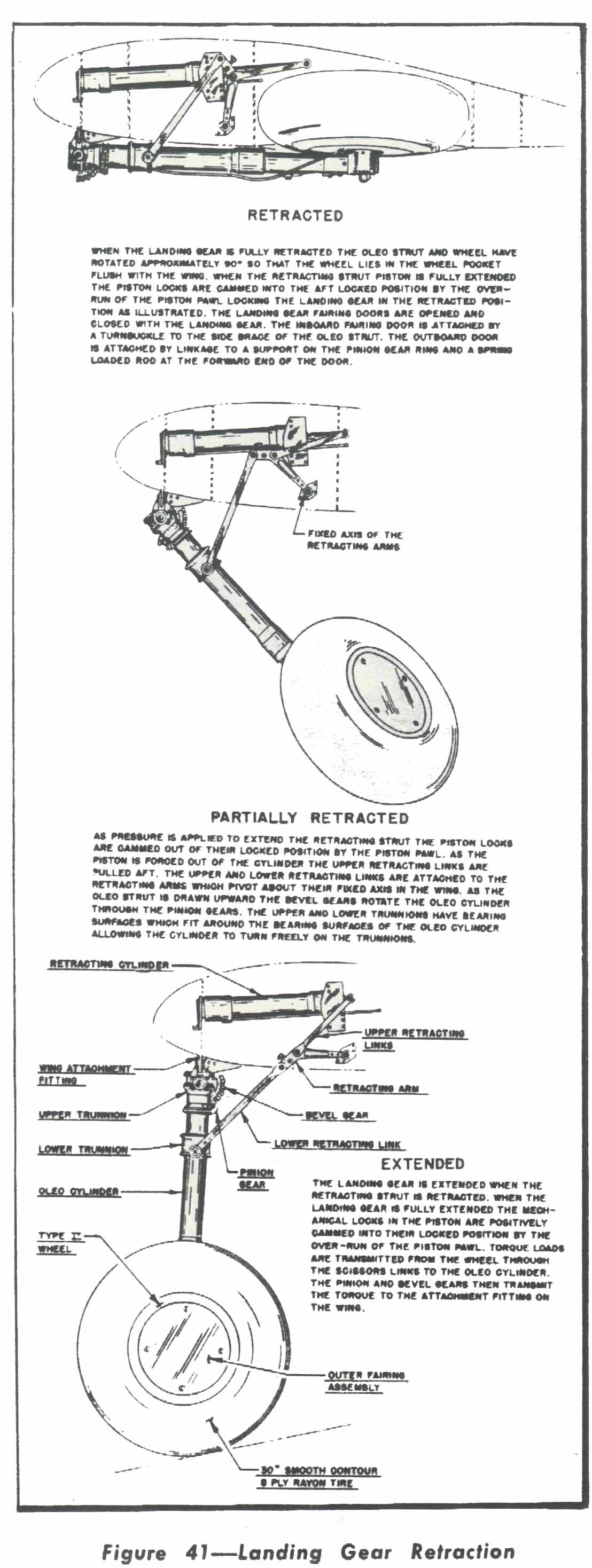 |
(c) Master Cylinder Unit. 1. GENERAL.-The brakes are actuated by the hydraulic brake master cylinders mounted on a support on the armor plate at Station 2A and actuated by a rod from the brake treadles. The brake cylinders and master cylinders are connected by flexible rubber hose and 5/16inch O.D. "Everdur" tubing. 2. DETAILED OPERATION OF THE MASTER CYLINDER UNIT-The views on figure 46 show the operation of the master cylinder unit when following the filling and bleeding procedure recom. mended by the manufacturer of, the unit. A description of the different views follows, reading from left to right: FIRST VIEW.-Unit in off (released) po. sition after being properly filled and bled, with the transfer valve closed. SECOND VIEW-Unit with the brake applied and with pressure in the system. THIRD VIEW-Unit in the parked position with the system under pressure. Same as second view, except that the force is maintained by the parking spring and ratchet instead of by the pressure on the brake treadle. (3) FILLING AND BLEEDING THE HY. DRAULIC BRAKE SYSTEM.-Figure 47 gives the method for filling and bleeding the brake system reconimended by the master cylinder manufacturer. (4) INSTALLATION AND DISASSEMBLY. (a) TO REMOVE THE LANDING GEAR ASSEMBLY FROM THE WING PANEL. 1. Disconnect the clevis end of the turnbuckle which controls the opening and closing of the inboard landing gear fairing door and the end of the cable from the outboard door to the support on the pinion gear ring. The inboard door turnbuckle is attached to the side brace and the outboard door cable is attached to a support on the underside of the oleo strut pinion gear. Disconnect the bearing end of the springloaded rod at the forward end of the outboard door. 2. Remove the screws attaching the landing gear leading edge fairing and outboard fairing door to the wing and remove the fairing. The leading edge section of the wing fillet must be removed to gain access to the inboard screws on the landing gear fairing at the leading edge. 3. Insert the jack point studs in the panel and jack the front and rear of the airplane until the landing gear wheels are off the ground. 4. Remove the bleeder screw at the brake Cylinder on the inner wheel fairing and drain the brake system. Disconnect the hydraulic brake hose at the fitting below the bleeder screw on the torque plate. Remove the two hose clamp fittings from their supports, one at the lower end of the oleo cylinder and the other at the lower trunnion. |