| AN 01-25CN-2 | PARAGRAPH 4 |
|
d. Remove the bleeder screw on the rear of the cylinder and drain the fluid from the hydraulic line and cylinder. e. Disconnect the brake hose at the fitting on the inner fairing. f. Pull the cotter pins and remove the bolts attaching the two levers, one at each end of the cylinder, to the two cylinder piston rods. g. Cut the lock wire on the cap screws at the base of the cylinder and remove the cap screws. This will free the brake cylinder from the torque plate and the cylinder can now be disassembled. 2. To disassemble the brake cylinder, proceed as follows: a. Remove the rubber boots, at either end of the cylinder. This will allow the piston rod, piston, and piston cup to be removed from each end of the cylinder. The piston cup spring may now be-removed and the cylinder is completely disassembled. 3. To assemble the brake cylinder. Before assembly the cylinder should be washed with alcohol and the pistons and cups lubricated with hydraulic brake fluid. Do not use mineral oil. a. Insert the spring in the cylinder and then the piston cups, one from either end, to fit over the spring. b. Next install the two pistons, one on either end. c. Install the rubber boots which will hold the pistons and cups in the cylinder. d. Attach the brake cylinder to the torque plate with the two cap screws and safety-wire the screws. e. Insert the piston rods into the holes in the boots and attach them to the brake shoe levers with the proper bolts. Safety the bolts in place with cotter pins. f. Connect the hydraulic hose to the cylinder fitting on the back of the torque plate. |
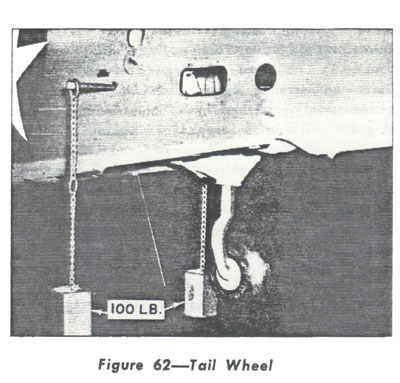 The brake system must now be serviced with fluid. The correct filling and bleeding procedure is outlined in figure 47, and should be followed to assure the efficient operation of the brake system. After the brake system has been properly filled and bled, it may be found necessary to ad. just the brake treadle to gain the maximum braking efficiency of the system. If the treadle adjustment is necessary, follow the procedure outlined in figure 45. b. TAIL WHEEL ASSEMBLY (Drawing No. 87-37-901). (1) GENERAL. (a) The tail wheel assembly consists of a standard steerable knuckle unit, equipped with a wheel, a 12½ inch diameter, 4-ply rayon, smooth-contour casing, statically grounded, and an air-oil strut. The wheel disengages its steering splines at 30° ± 2° and will then castor through 360°. The cables connecting the horn to the pedals are equipped with springs to reduce taxiing shocks in the pedals and the control system. When retracted, the tail wheel is enclosed by clamshell-shaped doors, which form the under surface of the fuselage about the wheel. The tire should be inflated to 60 p.s.i. (See Fig. 62.) |