| AN 01-25CN-2 | PARAGRAPH 5 & 6 |
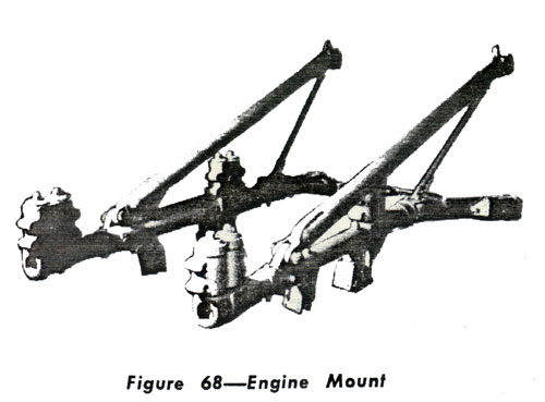 5. ENGINE SECTION. ENGINE MOUNT (Drawing No. 87-22-702). (1) DESCRIPTION.-The engine mount is constructed of steel tubing (X 4130) and aluminum alloy forging (24ST). The steel tubing has been heat treated to 150,000 psi. (See Fig. 68). (2) REMOVAL AND DISASSEMBLY: When removing the engine mount-fuselage bolts, use the engine mount bolt puller provided as a special tool. See Section III, Paragraph 5 of this Handbook. (3) MAINTENANCE REPAIRS-If damage to any of the tubing exceeds a bend of one three hundredth (1/300) of its length or a dent of more than one sixteenth (1/16) inch, it will be replaced. It will not be practical to repair any of the engine mount as it would necessitate reheat-treating the complete assembly. b. COWLING (Drawing No. 87-730-1001). (1) All cowl sections are spot welded or riveted aluminum alloy construction with the exception of the cowl immediately adjacent to the flame dampening exhaust stacks. The shroud cowl is of stainless steel construction. (See Fig. 69.) (2) The fuselage cowl between' Stations 1 and 2 is designed to permit ready access to the oil tank installation. (3) Cowl which must be frequently removed for servicing, such as the engine and fuselage cowls, are attached with Dzus fasteners. The semi-permanent cowl is attached with machine screws and bolts. |
6. POWER PLANT. a. ENGINE. (1) DESCRIPTION: One 12 cylinder, liquid cooled, Allison V-1710-81 (F-20R) engine is installed in this airplane (See Figs. 70, 71, and 72). (2) REMOVAL: The engine may be removed from the mount, or the engine and mount with radiators, etc. attached, may be removed from the airplane at the firewall. (See Figs. 73, 74, 75, and 76. ) (a) To remove the engine and mount from the airplane: 1. Remove side engine cowls by removing all Dzus fasteners. 2. Remove the lower engine cowl. 3. Remove the air filter box from the right side of the forward engine bulkhead. 4. Remove the top cowl as follows: a. Disconnect the left and right hot air duct hose f rom the hot air intake at the carburetor air intake box. b. Disconnect the carburetor air intake box from- the carburetor by loosening the wing nuts on each side of the carburetor. c. Disconnect the air filter control arm at the outside bell crank located on the top right of the firewall. d. Disconnect the carburetor air heat control arm at the bell crank located on the right side of the carburetor air intake box. e. Remove the two Reed and Prince screws holding the top cowling to the firewall and the four Reed -and Prince screws holding the top cowling to the forward engine bulkhead. 5. Remove the cowl flaps and formers by removing the cowl shutter channel as one unit. Part of the skin attached to the cowl by Reed and Prince screws will have to be removed in order to get at the cowl attaching bolts. 6. Remove the air exit duct by removing the three (3) screws at the rear of the coolers, the two bolts on top of the exit duct above the aft end of each cooler, the two (2) canvas seals from the coolant radiators to the exit ducts, the screw on each side of the aft end of the exit duct and the clip holding the vent lines to the rear of the exit duct. The exit duct can now be removed. |