| AN 01-25CN-2 | PARAGRAPH 1 & 2 | |
| HANDLING AND GENERAL MAINTENANCE INSTRUCTIONS |
|
1. ACCESS AND INSPECTION PROVISION. a. Access doors are shown in Fig. 16 and 17. These doors give access for adjustments and inspection purposes. 2. GROUND HANDLING. The tow rings are provided for handling the airplane on the ground, one on the inboard end of each landing gear axle. These two rings are shown in Fig. 18. If it is desired to hold the 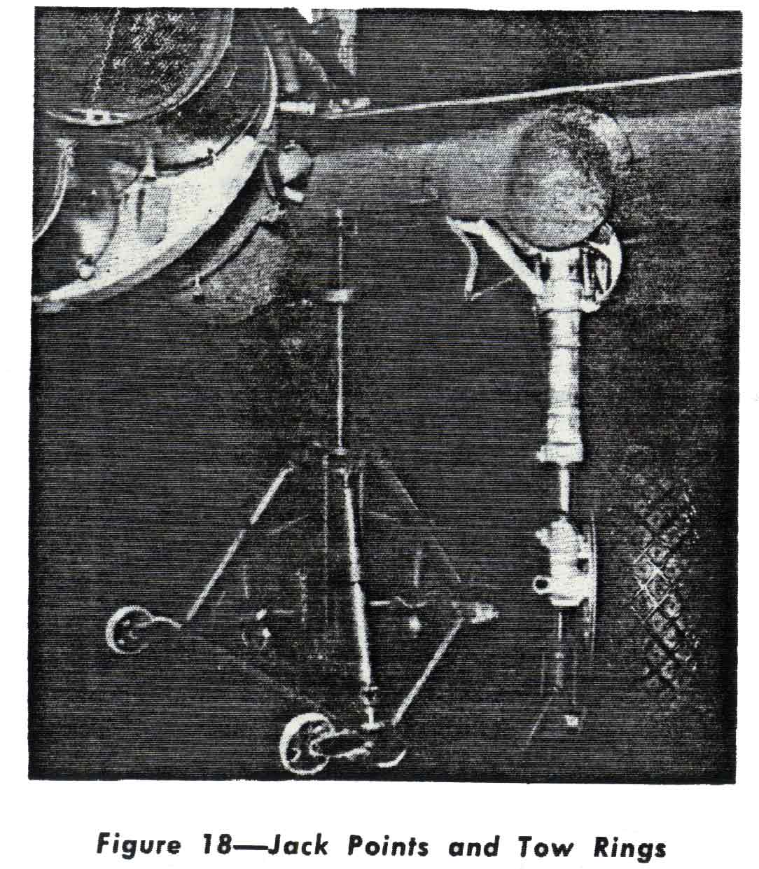 plane for engine run-up tests, pass a bar through the lift tube in the rear of the fuselage and tie down to an anchor point in the ground. Tie equal1y on each side of the fuselage so as not to apply any twisting moment to the fuselage. a. HOISTING-Refer to Section 11, Paragraph 2.a. b. JACKING ARRANGEMENT. (1) There are three jacking points to support the airplane while checking the landing gear and tail wheel retracting mechanism. One jack point stud is located on the under surface of each wing panel inboard of the landing gear and one jack point on the bottom of the fuselage aft of the tail wheel. (2) Additional jacking points are located on the bottom of each towing ring, on the inboard side of the landing gear axle, to support the forward end of the airplane while servicing the wheels and brakes. |
c. LEVELING. Six leveling lugs are located on the two longerons which form the cockpit sill. Two lugs for longitudinal leveling are located in the longeron on the right side, and two lugs for gun leveling are similarly located on the left side. The two lugs for lateral leveling are located on the sill, right and left sides inunediately aft of the windshield., A I/S-inch hole is drilled in the nose cone of the propeller spinner, concentric with the center line of the spinner, and a 10-32 inch nut plate is located on the center line of the fuselage just forward of the tail wheel doors, for plumb bob attachment when sighting the guns. d. TIE-DOWN - PARKING AND MOORING INSTRUCTIONS. (1) Tie-down rings are located in the under sur. face of. each wing between the outboard bulkhead and the removable wing tip. These rings are held in the retracted position in the wing by springs and are pulled down through slots by small tabs which protrude through the bottom surface of the wing. Decalco. manias inscribed "TIE-DOWN" indicate the location of these tabs. The tail lifting bar may be passed through the lift tube at the aft end of the fuselage to tie down the aft portion of the airplane. e.PARKING BRAKES AND SURFACE CONTROL HARNESS. (1) The parking brakes are set by pulling on the parking brake control button, located beneath the instrument panel on the left side, while holding both brake treadles depressed. Release the parking brakes by depressing the brake treadles. (2) The control surfaces are locked by rigging the parking harness (Drawing No. 87-530-1010) around the control stick. Attach the cables as shown in Fig. 19. If the hooks are painted, attach the green hooks to the pilot's seat and the red hooks to the rudder pedals. If the cables seem too short, adjust the rudder pedals to the full aft position and the seat in the down position. Attach the cables and raise the seat to remove the slack. |