| AN 01-25CN-2 | PARAGRAPH 1 | |
 |
||
|
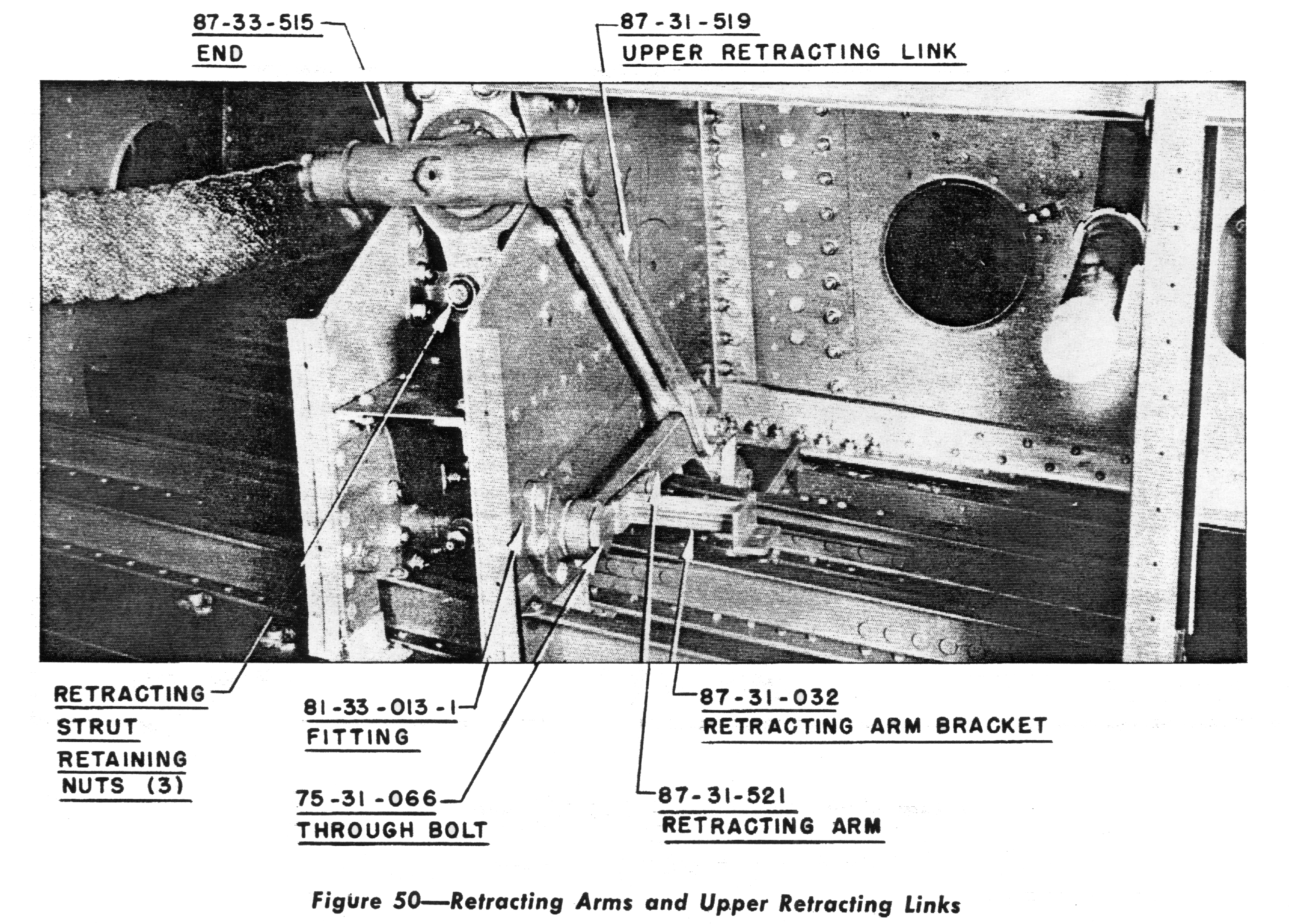
12. Disconnect the two hydraulic lines at the aft end of-the- retracting strut. 13. Remove the three nuts which attach the retracting cylinder in the wing and remove the cylinder by puffing it aft into the wheel pocket. 14. Working through the two lightening holes in web 3, at either side of the retracting strut cutout, remove the through bolt which attaches the retracting arms to the wing at the remote pivot points. 15. Move forward under the wing, pull the cotters and turn off the nuts attaching the lower retracting links to the lower oleo trunnion. With the retracting arms free in the wing there will be enough side play to remove the lower retracting links from the trunnion fittings. 16. Disconnect the side brace link at the wing, or at the oleo strut's lower trunnion if desired. 17. Remove the cotter pins, nuts, and bolt. |
from the wing attachment fittings and lower the oleo strut assembly from the wing. (See Fig. 51.) 18. The retracting arms may now be pulled far enough through the wing opening easily to remove the nuts and pull the attaching bolts of the tracting arms and lower retracting links. 19. Remove the upper retracting links and retracting arms from the wings as illustrated in Fig. 49. (b) TO DISASSEMBLE THE OLEO STRUT. 1. After the oleo strut assembly has been removed from the wing, vent the air pressure carefully and drain the hydraulic fluid by removing the Schrader plug. Place the oleo strut in a wooden block clamp to secure it from turning. Remove the six attaching bolts and lift the brake shoe and torque plate assembly from the axle, 2. Reverse the position of the oleo strut in the-wooden blmk clamp and Pull,the cotter pin from |
|