| AN 01-25CN-2 | PARAGRAPH 1 | |
| SECTION IV | ||
| MAJOR COMPONENT PARTS AND INSTALLATION |
 |
||
|
the plunger nut. Turn the plunger nut off with a socket wrench and remove the upper trunnion cap. (See Fig. 52.) 3. After the upper trunnion cap is removed, pull the upper trunnion assembly, including the bevel gear and wing attachment fittings" off the oleo strut. 4. If the side brace has been removed with the oleo strut assembly, pull the cotter pin, loosen the nut, and remove the bolt that attaches the side brace to the lower trunnion. Remove the side brace from the trunnion. |
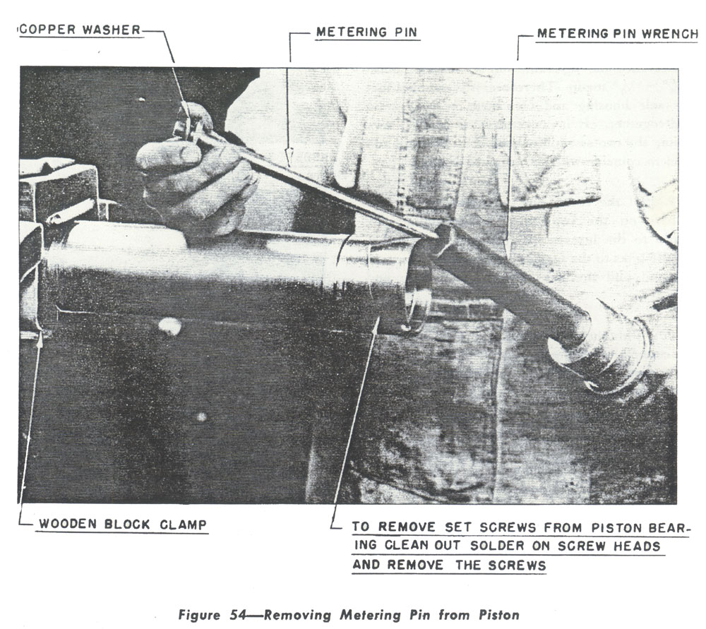
5. Unscrew the eight cap screws holding the two lower trunnion halves together and pull the trunnion halves from the oleo strut. 6. Remove the two lower trunnion facer plates and the four segments. 7. Putt the cotter pins and remove the nuts and washers from the four pinion gear attaching bolts, pull the bolts, and remove the two segments and the support. The shims will come out with the pinion gear. 8. Reverse the oleo strut cylinder in the wooden block clamp, pull the cotters, remove the nuts, |
|