| AN 01-25CN-2 | PARAGRAPH 1 |
|
and pull out the two bolts which attach the oleo piston to the axle housing. When the axle housing and oleo strut are assembled, these two parts are fittied together with no clearance and jig-reamed to set the axle housing for ~/4* - 3/4* toe-in. Therefore, it is essential that the same axle housing and oleo strut be always reassembled together. If it is necessary to install a new axle housing the two assemblies should be lined up and jig-reamed to coincide with the original assembly. 9. Pull the cotter pins and remove the nuts and washers on the two bolts, one attaching the scissor links to the lugs on the piston and the other attaching the links to the lugs on the cylinder. Remove the bolts and pull the links free of the piston and cylinder lugs. 10. With the oleo cylinder secure in a wooden block clamp, loosen the set screw on the cylinder and turn the packing gland nut completely out of the cylinder with a spanner wrench. 11. Pull the piston assembly from the end of the cylinder. The piston assembly is composed of the gland nut, packing and packing rings, piston sleeve, piston bearing, and metering pin. (See Fig. 53.) 12. If it is desired to remove the metering pin, place the piston assembly in a wooden block clamp and lock the clamp in a vise. Insert the metering pin wrench (Drawing No. 87-88-031) into the piston at the bearing end and unscrew the metering pin. Re. move the metering pin and wrench and pull the metering pin from the wrench as illustrated in Figure 54.
13. While the piston is in the wooden clamp and secured in a vise, remove the solder from the three lock screws on the piston bearing, either by digging the solder out or by applying just enough heat to melt it away. Remove the screws. |
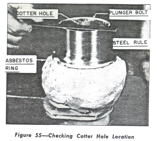 14. Use a spanner wrench and turn the piston bearing off the piston. The sleeve, packing ring, packing and gland nut can now be slid off the piston. The piston is now completely disassembled as illustrated in figure 53. 15. If it is desired to remove the plunger from the oleo strut, place the oleo strut in a vertical position in a vise as illustrated in figure 55. Mix some asbestos with water until a thick mixture is obtained, and mold a generous ring of asbestos around the oleo as shown in figure 55. This will prevent the heat from the torch, when applied to melt the solder joint, from going down into the oleo cylinder. 16. Apply heat from a torch and melt the solder. 17. Free the oleo cylinder from the vise and turn the cylinder upside down so that the melted solder will run out into a container. Now the plunger can be turned out of the cylinder with a spanner wrench without any flowage of solder into the cylinder when the plunger is removed. The oleo strut is now completely disassembled for inspection and servicing. |
||||||||