| AN 01-25CN-2 | PARAGRAPH 5 & 6 |
(6) TO ASSEMBLE THE AFT SECTION OF THE PROPELLER SPINNER TO THE PROPELLER HUB-Reverse the procedure noted above.
(7) TO ASSEMBLE PROPELLER BLADES TO PROPELLER HUB. (a) When this assembly takes place, make sure that the threads of the hub and blade are clean and free from any metal chips or other foreign matter. (See Pig 78.) Coat the thread with a mixture of 707c. white lead and 30%~ lubricating oil. Remove the locking plates which have been temporarily installed on the nuts of the loose blades. The No. I blade is numbered on the retaining nut and this blade must be assembled in the No. I hub barrel. The No. 1 blade is opposite the master splice of the hub, and the No. 2 and No. 3 blades are placed clockwise in the hub as facing the front of the unit. (See Fig. 81.) Each blade has a gear backlash shim. These shims are not interchangeable. Place the blade shim in the correct hub barrel with the chamfer towards the hub center. (b) MASTER LUG AND BLADE NUT SLOT-Insert the propeller blade into the hub barrel. Screw each blade nut into the hub until one-half of the threads are engaged. With someone exerting an outward pull on the blade, tighten the blade nut with the spanner wrench provided and approximately a ten pound brass hammer, until the paint marks on the slots of the blade nut and,hub line up. (See Fig. 79.) if there are no paint marks, tighten the blade nut until it is barely possible to turn the blade by hand. A check should be made with a wooden blade wrench to make sure the blade will rotate after bringing the two slots in line with each other. Insert the lock lug in lined up slots, screw lug into slots securely and lock with lock wire.
|
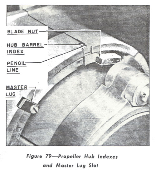 (c) HUB BARREL INDEXES.-The propeller hub barrels are indexed on the face or front side of hub in order to correctly position the blade sector gear for receiving the power unit. Since the indexes on the blade sleeve have proven more or less inaccurate by field personnel, the following method which is now being used, has proven itself simple and sufficiently accurate. Proceed as follows: with the hub and blade assembly on a flat surface, with hub face up, place a straight edge across the face of hub from the hub barrel index to the center of the power unit contact directly opposite on the other side of hub. Draw a straight pencil line along the straight edge from the hub barrel index to the engine shaft opening of the hub. This can be repeated for the second index or hub barrel. When drawing a line for the third index, the line must run between the two power unit contacts which are directly opposite the third barrel. (See Fig. 79.) After these pencil lines have been drawn, a vertical line is dropped into the engine shaft opening in order to bring the pencil lines close to the teeth of the blade sector gear. |