| AN 01-25CN-2 | PARAGRAPH 6 |
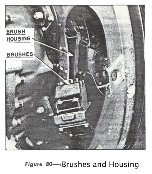
(8) TO ASSEMBLE PROPELLER TO ENGINE SHAFT. (d) There are two points to make sure of when placing the propeller and hub assembly on engine propeller shaft, namely: make sure that the brushes have been removed from brush housing (remove the two safety pins, unsnap and lift out brush unit) (see Fig. 80), and that the engine propeller shaft has been turned so that the master spline is at the bottom. Have the master spline of the hub at the bottom so that the matching or alignment of these two master splines will be easier to align. (See Fig. 81.) Clean engine propeller shaft with varnoline and then coat the splines with castor oil. The shaft threads are painted or coated with anti-seize thread lube. (b) PROPELLER SHAFT NUT-just before assembling propeller to engine shaft, install grease seal, split cone, and propeller shaft nut in hub. |
(c) BRUSHES ON HUB SLIP RINGS-At this point, apply persian blue to the four top brushes of the brush unit and place brushes back into the brush housing. Snap into place with the top and bottom snaps. Swing the propeller blades backwards and forwards just a trifle, this will show clearly how the brushes are riding on the hub slip rings. 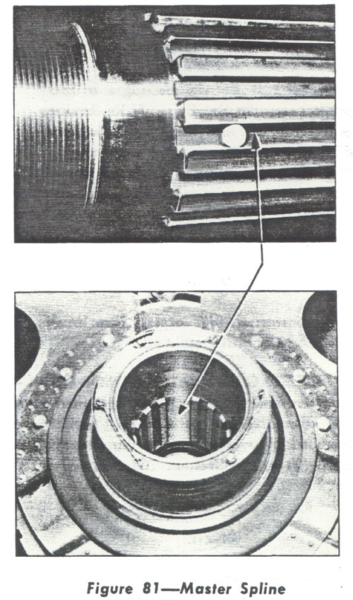 |